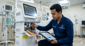
In the high-stakes environment of an Intensive Care Unit (ICU), the mechanical ventilator is the most critical life-support device. As a Biomedical Engineer working in the field since 2017, I have encountered countless “Alarm” situations where every second counts. Understanding the technical architecture of these machines is not just about maintenance; it is about patient safety.
This guide explores the most common ventilator errors, their root engineering causes, and the professional calibration steps required to resolve them.
Modern ventilators are masterpieces of fluid dynamics and electronic control. They rely on high-precision proportional valves, pressure transducers, and flow sensors. When these components fall out of sync, the system triggers alarms. For an engineer, troubleshooting begins with isolating whether the fault is Pneumatic (gas supply/leaks) or Electronic (sensor failure/mainboard issues).
The Low Pressure Alarm is perhaps the most frequent notification. While clinicians often check for patient disconnection, the engineering cause often lies deeper.
Exhalation Valve Failure: A worn-out silicone diaphragm in the exhalation valve can prevent the system from maintaining PEEP (Positive End-Expiratory Pressure).
Internal Leakage: Perforations in the internal tubing or a loose connection at the humidifier water chamber.
Transducer Drift: The inspiratory pressure transducer may be sending incorrect voltage signals to the CPU.
Perform a Circuit Leak Test (SST/EST). If the leak persists despite changing the patient circuit, inspect the internal O-rings of the inspiratory and expiratory blocks.
When a ventilator displays “O2 Sensor Error” or shows a significant deviation between the set $FiO_{2}$ and the measured $FiO_{2}$, the oxygen fuel cell is usually the culprit.
Most modern ventilators use galvanic oxygen sensors. These are essentially batteries that consume themselves over time. Since my start in the field in 2017, I’ve noted that these sensors typically last 12–18 months depending on usage and humidity levels.
100% O2 Calibration: Access the service menu and perform a pure oxygen calibration.
Room Air Calibration: Expose the sensor to 21% ambient air to reset the baseline voltage.
Replacement: If the sensor output voltage falls below the manufacturer’s threshold (usually < 7mV in room air), it must be replaced.
Flow sensors (Hot-wire or Differential Pressure) are extremely sensitive. If the ventilator reports “Flow Sensor Error,” the patient’s Tidal Volume (Vt) measurements will be unreliable.
Moisture Contamination: Moisture from the humidifier often settles on the flow sensor wires, causing erratic readings.
Calibration: Use a certified Pneumatic Calibration Syringe or an external Flow Analyzer to verify that the flow sensor’s digital output matches the physical gas displacement.
Cleaning: Use 70% Isopropyl Alcohol for ultrasonic cleaning if the manufacturer allows, or replace the disposable flow sensor.
Many engineers overlook the internal battery and power supply unit (PSU). A ventilator that shuts down immediately after a power failure—despite being plugged in—has a compromised battery bank.
Battery Cycle Life: Lead-acid or Li-ion batteries in medical equipment should be load-tested annually.
SRAM Battery: If the ventilator “loses memory” of its settings or date/time after a reboot, the small CMOS/SRAM battery on the motherboard needs replacement.
To ensure the machine is “Patient Ready,” every Biomedical Engineer should follow this sequence after a repair:
Electrical Safety Test (EST): Ensure leakage current is within the limits of IEC 60601-1.
Pressure Calibration: Use a calibrated pressure gauge to verify the accuracy of the internal transducers at 10, 20, and 40 $cmH_{2}O$.
Volume Verification: Connect a “Test Lung” and verify that the delivered Tidal Volume is within $\pm 10\%$ of the set value.
Alarm Verification: Manually trigger high-pressure and low-battery alarms to ensure the auditory and visual indicators are functional.
Ventilator maintenance is a blend of precision engineering and clinical responsibility. Having worked with various brands and models since 2017, I’ve learned that a proactive Preventive Maintenance (PM) schedule is the best way to avoid these errors.
For technical consultations or specific service manual inquiries, feel free to contact me.
Md. Monir Hossen
Biomedical Engineer
Email: monir@biomedicaldiary.com